Electrochemical micromachining of nitinol by confined-etchant-layer technique
MA X-Z, ZHANG L, CAO G-H, et al.[J].
Electrochimica Acta, 2007, 52(12): 4191-6.

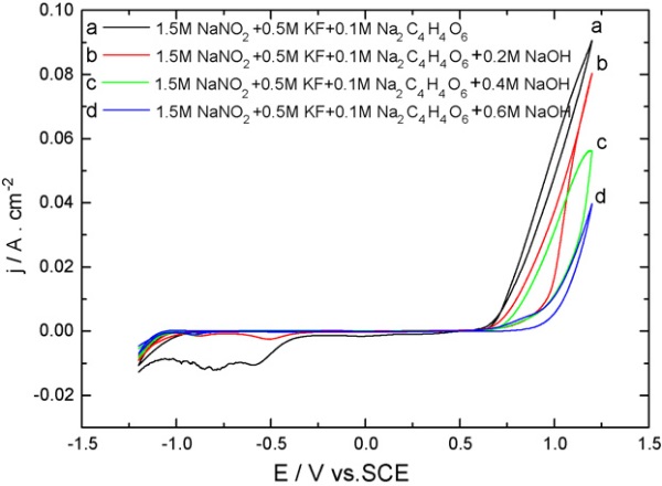
Fig. 1. Cyclic voltammograms of a polycrystalline Pt electrode in the etching system in the presence of different concentrations of NaOH. Scan rate:50 mV/s. Curve a, 1.5M NaNO2 + 0.5M KF + 0.1M Na2C4H4O6; curve b, 1.5M NaNO2 + 0.5M KF + 0.2M NaOH + 0.1M Na2C4H4O6; curve c,1.5M NaNO2 + 0.5M KF + 0.4M NaOH + 0.1M Na2C4H4O6; curve d, 1.5M NaNO2 + 0.5M KF + 0.6M NaOH + 0.1M Na2C4H4O6.

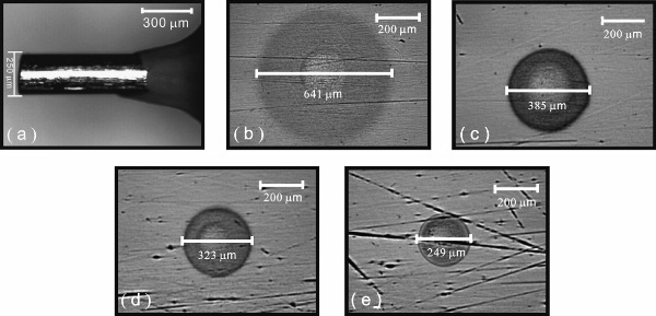
Fig. 2. Microscope images of the microcylindrical electrode (a), and of etched microstructures on nitinol in solutions of (b) 1.5M NaNO2 + 0.5M KF + 0.1M C4H4O6Na2, (c) 1.5M NaNO2 + 0.5M KF + 0.2M NaOH + 0.1M C4H4O6Na2, (d) 1.5M NaNO2 + 0.5M KF + 0.4M NaOH + 0.1M C4H4O6Na2 and (e) 1.5M NaNO2 + 0.5M KF + 0.6M NaOH + 0.1M C4H4O6Na2. The potential of the mold was controlled at 1.0V. The distance between the mold and the nitinol was controlled at 200 nm.

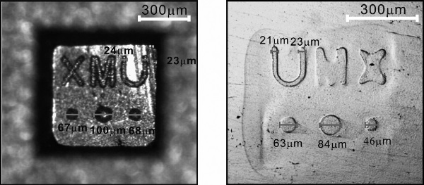
Fig. 3. Microscope images of a complex 3D pattern and of corresponding etched microstructures on a Ni–Ti alloy. The potential of the mold was controlled at 1.0V. The electrolyte was 1.5M NaNO2 + 0.5M KF + 0.4M NaOH + 0.1M C4H6O2Na2. The distance between the mold and the nitinol was 200 nm.
文章链接:http://www.sciencedirect.com/science/article/pii/S0013468606012400